SFORMO
SFORMO — a Blender add-on for mould-making. Point it at a mesh and it answers three questions in order: can this be cast at all, how many pieces will the mould take, and where does it split. Then it builds the actual blocks — hollowed, split, keyed, vented, numbered — as watertight solids you can export and print. The name is Italian for the act of taking a thing out of its mould.
It installs from sformo.zip via Preferences ▸ Add-ons ▸ Install from Disk, and lives in the 3D viewport sidebar (N) under a Sformo tab.
This page is the whole manual.
Contents
The idea — a mould is a set of pull directions
Every face of a form has to be able to leave the mould along some direction. A two-part mould offers two, opposite. A coopered mould offers one per stave, radiating. A press mould offers exactly one. So the part count is really the question: what is the smallest set of pull directions that covers every face — plus whatever caps the ends.
That framing is what lets Sformo walk a ladder from simple to complex and stop at the first rung that works:
one-part press → two-part → radial / staved
With Strategy on Auto (simplest mould) it tries each in turn and reports the first that releases cleanly. You can also force a rung to see what it would cost.
Analyzing
Set the Axis — for a two-part mould this is the pull direction, for a radial mould it is the axis of revolution. The camera button beside it takes the axis from your current view, which is usually faster than thinking in X/Y/Z. Min Draft is the shallowest angle you will accept before a face counts as dragging (2° is a sensible default for a rigid printed mould; raise it for something you want to release sweetly).
Then press Analyze.
Apply your modifiers first. Sformo analyses the base mesh and will warn you if a modifier is still live. A Subdivision or Solidify that isn't applied means you are being told about a shape you aren't going to cast.
The mesh must be clean and closed. Internal faces are the classic trap: joining two primitives with Ctrl+J leaves both their interiors inside the form, and every one of those hidden faces reports as an undercut. Use a boolean union, not a join. Non-manifold or self-intersecting geometry produces false undercuts in the same way.
The colour key
The result is painted straight onto the form as a translucent coat — a GPU overlay that writes nothing into your mesh, so there is nothing to clean up afterwards. (Untick GPU Overlay and it bakes a colour attribute instead, which is what you want if you intend to render the diagnosis. Clear Heatmap removes either.)
For a two-part pull:
| green | releases toward +pull |
| blue | releases toward −pull |
| white | the parting band — the silhouette itself |
| yellow | low draft — it will come out, but it will drag |
| red | undercut — this locks the mould |
For a radial mould: green releases, yellow drags, red is undercut, and grey is an end cap — a face square to the axis, which no stave can release and which needs a plate.
The panel keeps a live legend under Colour Key, so you never have to remember which is which.
Reading the numbers
Moldable % is by area, not by face count, which is the honest measure — a thousand tiny undercut faces in a nostril matter far less than one broad locked shelf.
Undercut regions counts connected undercut patches, because that is what actually becomes a loose piece or a side core. Carved and scanned surfaces shatter into specks — lip corners, hair partings, tool chatter — so anything under about a quarter of a percent of the surface is set aside and shown as (+N negligible). If you see "2 + 6 side-cores", it is the 6 significant regions being counted, not the confetti.
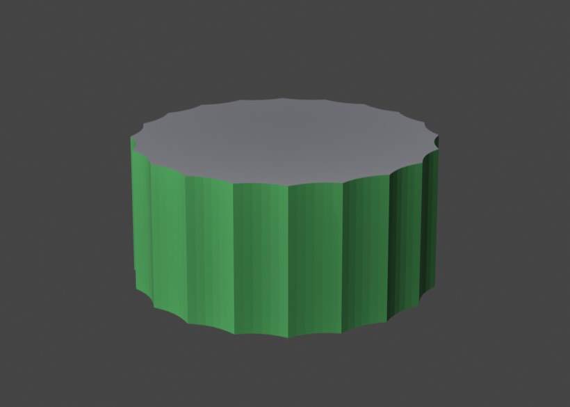
Red is not automatically a verdict. A flute is a concave groove, so under a sideways pull its far wall genuinely blocks the near one — a fluted drum is honestly not two-part mouldable on any axis, and the red is correct. That is the tool telling you to go radial, not the tool being wrong.
Two-part is not one-part. The underside of a mushroom cap is an undercut for a press mould and perfectly fine in a two-part mould, because the bottom half releases it. Don't carry 3D-printing overhang instincts into the reading.
Find Best Axis searches a hemisphere of pull directions for the one with least undercut. It is off by default because it is n times the work — on a 79 000-face retopo head, an ordinary analysis takes about 4 seconds and the axis search takes 13. Leave it off while you are exploring and switch it on once.
Parting lines
Suggest Parting Lines marks the split as seams on the mesh plus a SFORMO_parting vertex group. Trace Parting Curves goes further and builds an editable curve object, <name>_parting, that you can grab and reshape — the start of a stepped or curved parting surface.
The line is found as the boundary between the two halves rather than by hunting for a ridge of faces, so on a closed mesh it comes out as closed loops by construction. On organic forms expect it to be honest rather than tidy: a scanned head gives several loops, not one elegant seam.
Flat regions parallel to the pull — the lid of a plain cylinder — have no silhouette to follow, so they are cut by position along the pull instead. That is the right answer, but it is why the curve sometimes runs straight across a flat face where you might have expected it to detour.
Building the blocks
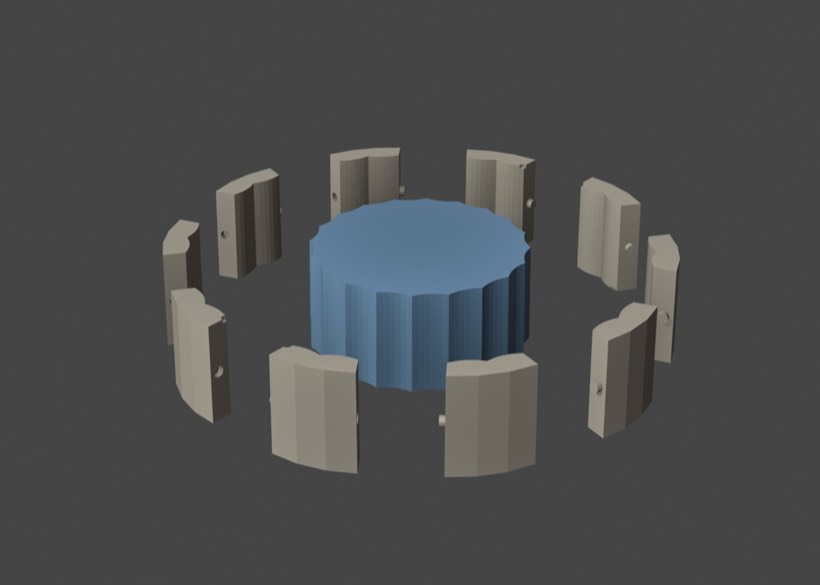
Build Mold Blocks makes the real thing into a fresh <name>_mold collection: the block, minus the model, split, keyed, drafted, vented and numbered. Two paths, chosen by the strategy — flat halves for a two-part pull, a ring of staves for a radial one.
| control | what it does |
|---|---|
| Wall % | mould wall thickness, as a % of the model's size |
| Reg. Keys · Key % of Wall | how many registration pegs, and how fat |
| Clearance | the print fit gap on every socket, in real millimetres |
| Draft° | draft on the outer walls and on every channel |
| Vents · Vent % | air escapes rising from the high points of the cavity |
| Pour Spout · Spout % | the sprue, straight down into the top of the cavity |
| Seam Keys | registration across the stave seams |
| End Plates | top and bottom caps for a radial mould |
| Number Pieces · Number mm | engrave the assembly order into each piece |
Clearance is in real millimetres, and deliberately does not scale with the model. A fit gap is a property of your printer and your material, not of the sculpture — 0.3 mm is 0.3 mm whether the drum is 40 cm or 4 m. Use 0.2–0.3 for a well-tuned FDM machine, 0.4–0.5 if you want a loose hand-fit or you're printing something that shrinks (PETG, ASA, anything glass-filled), and 0.1–0.15 for resin, which holds detail far tighter. If your first print's pegs won't seat, raise it by 0.1 and print one stave to test rather than the whole set.
Key % of Wall is a fraction of the wall, not of the model, because that is the only dimension a peg actually has to live inside. It seats at mid-wall and needs half again its own radius of material around it, which puts the hard ceiling at a third of the wall — so the slider stops at 33%. 25% is a solid key with room to spare. Sizing keys against the model was the old behaviour and it had a nasty failure: thinning the wall silently made every key unbuildable.
Registration
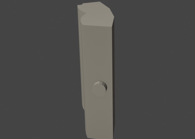
Every peg straddles its seam — half of it stands proud of one piece, and the matching socket, cut at radius-plus-clearance, is taken out of its neighbour. A peg that sits wholly inside its own half registers nothing, which is a mistake worth knowing about because it looks perfectly convincing in the viewport.
On a two-part mould the pegs are spread across the flash land outside the cavity, as far from the form and from each other as they will go. On a staved mould one key sits on each seam.
Knowing which piece is which
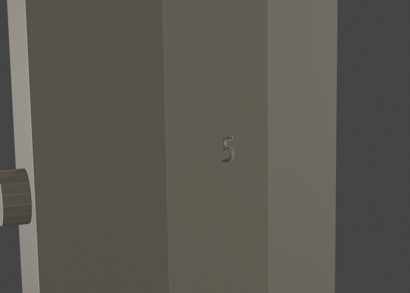
Number Pieces engraves an assembly number into the back of every piece, counting in the order they go together — for a staved mould, around the axis.
This matters more than it sounds. Once every seam carries a key, the pieces stop being interchangeable: each one has to arrive between two neighbours that are already seated, and the last one drops into a socket on both sides at once. Ten near-identical staves in a heap on the bench is a puzzle you have to solve twice — once to work out the order, and again the next time you cast.
The digits go on the back deliberately. Anything on the cavity wall would print itself into the cast, in reverse; anything on a parting face would hold the piece off its seat by exactly the height of the lettering. They are cut in rather than raised, so nothing snaps off in handling and the pieces still stack flat in the box.
Number mm is real millimetres, for the same reason Clearance is: legibility belongs to the printer, not the sculpture. Below about 5 mm an FDM nozzle stops holding the shape of a numeral and you get a blob with a hole in it. 10–16 mm reads across a workbench. The cut depth follows the height — a fifth of it, never under 1 mm — because a shallower engraving reads as a scratch and disappears under a layer of print fuzz or a coat of release agent.
On a ring of identical staves the numbers are a convenience. On a mould with genuinely different pieces — side cores, a stepped parting surface, anything asymmetric — they are the difference between a job and a jigsaw. Leave them on.
Staves, and where the seams fall
For a coopered mould the seams belong on the arris ridges — the crests between flutes — because a seam in the bottom of a hollow leaves a witness line exactly where the eye goes, and neither side drains cleanly.
That means the stave count has to divide the flute count. A twenty-flute drum can be split into 2, 4, 5, 10 or 20 staves and every seam will land on a ridge; ask for 3 and the boundaries fall back to even spacing, straight through the middle of a flute. Leave Staves at 0 and Sformo picks the smallest count that both releases and divides. Set it yourself when you want bigger or smaller pieces — which, in practice, usually means pieces that fit the printer.
Sizing for the bed is the thing that decides stave count in real work. A 438 mm drum at 4 staves gives pieces about 350 × 329 × 198 mm — fine on a Prusa XL, too big for an MK4S. The same drum at 10 staves gives roughly 198 × 165 × 124 mm, which fits both. More staves also means more seams to clean up on the cast, so take the smallest count that fits your machine.
End plates span the full outer diameter, which makes them far and away the largest pieces — that same drum wants a 657 mm disc, unprintable on anything. For a drum that stacks into a column you don't want them anyway: turn End Plates off and print the ring only.
The build checks itself
A failed boolean does not raise an error — it hands back a plausible-looking object that is quietly not a solid. So the builder inspects its own output and tells you: "— all watertight", or a warning naming the pieces that aren't. Believe the warning; a piece that isn't closed will slice into nonsense.
If a seam key can't be placed the build says so too, with the arithmetic, rather than silently giving you a mould with no registration. The report line counts everything it made: staves, plates, seam keys, vents, numbers.
Getting it out
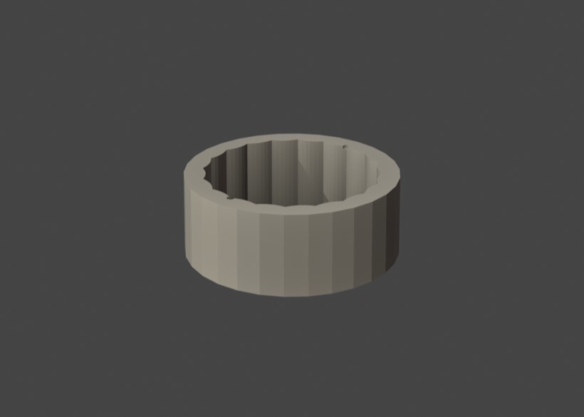
Explode % slides the finished pieces apart along the direction each one opens, so you can look inside the mould and see whether the cavity is what you meant. It is purely a view control and it is live — drag it back to 0 and the pieces are exactly where they belong. Zero is the export position.
Export Mold as STL writes every piece as its own .stl into a folder you choose, at Explode 0 regardless of what the slider is showing.
Export scopes the job: This Mold (click any one piece and get that whole mould), Selected Pieces Only, or All Molds in File. Default is the first, because a .blend accumulates moulds and you do not want last month's test cylinder landing in the folder you're about to slice.
STL files carry no unit. Every slicer reads the raw numbers as millimetres, full stop. If you model at Blender's default of 1 unit = 1 metre, a 0.33-unit stave arrives in PrusaSlicer as a 0.33 mm speck — the classic "why is my model microscopic" moment. The Scale to mm field is the fix, and it now reads your scene's Unit Scale and fills itself in (1000 for a metre-scaled scene). The dialog shows you the largest piece in millimetres before it writes anything, so check that number and you can't get it wrong.
Blender's Scene ▸ Units ▸ Unit Scale does not affect STL export at all — it only relabels the numbers in the N-panel. Worse, the exporter's own Scene Unit option applies it in the wrong direction and makes a millimetre-configured scene come out a thousand times smaller. Sformo pins that option off and uses an explicit scale instead. If your N-panel dimensions look wrong too, set Unit Scale back to 1.0.
When it goes wrong
"Mesh changed since Analyze — run Analyze again." The per-face results are indexed to the geometry, so editing invalidates them. Re-analyze. (This is also why the overlay quietly stops drawing when the mesh no longer matches, rather than showing you a heatmap that is a lie.)
"No silhouette found for this pull direction." You are pulling a form along an axis where nothing changes facing — a cylinder along its own axis, for instance. Correct behaviour; pick a perpendicular axis.
"Silhouette is not planar (spread …)" A flat two-part split only works if the whole silhouette lies in one plane. Organic forms rarely do — a scanned head runs 40–50% off-plane — so the warning means the flat split will leave undercuts and you want a stepped parting surface, more pieces, or a different rung of the ladder.
Analysis results vanish when you rename an object. Results are keyed by object name. Re-analyze.
The panel, in order
| Strategy · Axis · Min Draft · Staves · Find Best Axis · GPU Overlay | set up |
| Analyze | the diagnosis |
| Suggest Parting Lines · Select Undercuts · Trace Parting Curves · Clear Heatmap | the line |
| Wall % · Spout % · Reg. Keys · Key % of Wall · Clearance mm · Draft° · Vents · Vent % · Pour Spout · Seam Keys · End Plates · Number Pieces · Number mm | the mould |
| Build Mold Blocks · Explode % · Export Mold as STL | the object |
Lives in TROY/SFORMO (sformo/__init__.py, one file; sformo.zip to install). Related: FRIEZE is the other Blender add-on, watching sculpt sessions rather than casting them; METOPE carves the reliefs that end up needing moulds, and has its own undercut logic for the CNC side.